"There shall be light..."
(For this article I used information from the microchip website)
In today's article we are going to learn how to say "Hello world" in the language of micro-controllers, in other words how to give light to a led. We are going to need:
- Micro-controller (I use PIC16F690)
- LED
- Resistor (about 250 ohms is fine)
- And off course power, 5Vdc
First of all take a look on the schematic of the circuit (I used PROTEUS software, more here):
 |
| Led circuit |
- Initialization of the ports (set I/Os, analogs and digitals)
- Main function (main program, call subroutines)
- Back to the Main Function.
Initialization
- Initialization
- bsf STATUS, RP0
- bcf STATUS, RP1 ;bank 1
- movlw 0xff
- movwf TRISA ;PORTA is input
- clrf TRISB ;PORTB is output
- clrf TRISC ;PORTC is output
- bcf STATUS, RP0
- bsf STATUS, RP1 ;bank 2
- clrf ANSEL
- clrf ANSELH ;set all I/Os as digitals
- bcf STATUS, RP1 ;bank0
- clrf PORTC
- clrf PORTB
- return
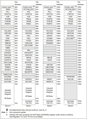
Before I try to explain the code above, I think you have to know more about the data memory organization of the PIC16F690.(Below its a part of the pdf file located at the microchip website)
"...The data memory is partitioned into four banks which contain the General Purpose Registers (GPR) and the Special Function Registers (SFR). The Special Function Registers are located in the first 32 locations of each bank. Register locations 20h-7Fh in Bank 0 and A0h-EFh (A0-BF, PIC16F687 only) in Bank 1 are General Purpose Registers, implemented as static RAM. Register locations F0h-FFh in Bank 1, 170h-17Fh in Bank 2 and 1F0h-1FFh in Bank 3 point to addresses 70h-7Fh in Bank 0. Other General Purpose Resisters (GPR) are also available in Bank 1 and Bank 2, depending on the device. All other RAM is unimplemented and returns ‘0’ when read. RP<1:0> (STATUS<6:5>) are the bank select bits:
RP1 RP00 0 → Bank 0 is selected0 1 → Bank 1 is selected1 0 → Bank 2 is selected1 1 → Bank 3 is selected
 |
The register TRISA:
Now we know what TRISA is lets go back to the initial code:
movlw 00xF --> move inside W (the accumulator) 0xFF (hexademixal format)
movwf TRISA --> move W into TRISA
After these two commands the contents of TRISA will be: xx11 1111. So the corresponding pins of the PORTA will be set as inputs.
We keep on with lines 6 and 7:
clrf TRISB --> clrf (clear register ) TRISB <--0x00
clrf TRISC -->TRISB <--0x00
By clearing these two registers, TRISB and TRISC we are setting the corresponding ports, PORTB and PORTC as outputs.
At this point it is a good idea to make an overview of what we saw until now. First we set the entire PORTA as input by setting all the bits of the register TRISA, next we set the ports B and C as outputs by unssetting all the bits of the registers TRISB and TRISC. This is the first part of the initialization.
The second part is by setting the type of the I/Os, analog or digital. To do that we have to modify the contents of ANSEL and ANSELH registers.
ANSEL:
ANSELH:
At the lines 8 and 9 we select the bank 2 where the registers ANSEL and ANSELH can be found. And then (lines 10 and 11) we clear (clrf) the contents of those registers in order to make all the pins (ANS0-ANS11) digital I/Os. The next 3 lines is a rule of mine always return to bank 0, and always clear the output ports before leaving the initialization.
Main function (main program, call subroutines)
The main function isn't nothing more than this:
- start
- ; remaining code goes here
- call Initialization
- loop
- bsf PORTC, 0
- goto loop
Line 1: is nothing more than a label, when we want to jump to a different part of our code we have to redirect the PC (program counter) to the address of the memory cell that stores the first command of that part of code, so you can remember all the address (in a hex format) or you can put labels (like we do) and let the assembler do all the work.
Line 2: is comments, everything in the same line after the ; are overlooked by the assembler.
Line 3: Using the command call we redirect the PC to the subroutine with name Initialization. Don't forget to end every subroutine with the return command.
Line 4: Another label.
Line 5: Finally the magic code that will give light to led, the command bsf, it can be translated into "set bit <0> of register PORTC".
Line 6: With the command goto we redirect the PC to the specific memory location depending of the label after the command. The reason we do that is to keep the PC from not leaving that part of code.(that's the third part Back to the Main Function.)
If everything is ok a hex file (among others) will be created. That file (my_project_name.hex) we are going to use with the simulation software (proteus). So open PROTEUS, design the circuit and:
- Double click on microcontroller symbol.
- Click the browse button next to "Program File" text box.
- Browse for the hex file, when you find it select it and click ok.
- When you are ready, click on the "Run" button and the simulation will start.
If everything is ok you should see something like that:
That's all for today!!!
(you can find all the files under this link.)


No comments:
Post a Comment