Action After event
Today we are going create a simple program that will enable a led after an event (button). So, we are going to need:1. A Micro controller (i usually use PIC16F690)
2. Resistor, led, push button
3. Power 5 Vdc
For this program I created the flowchart below in order to help you understand the “flow” of the program. (it is recommended for every program a flow chart to be created)
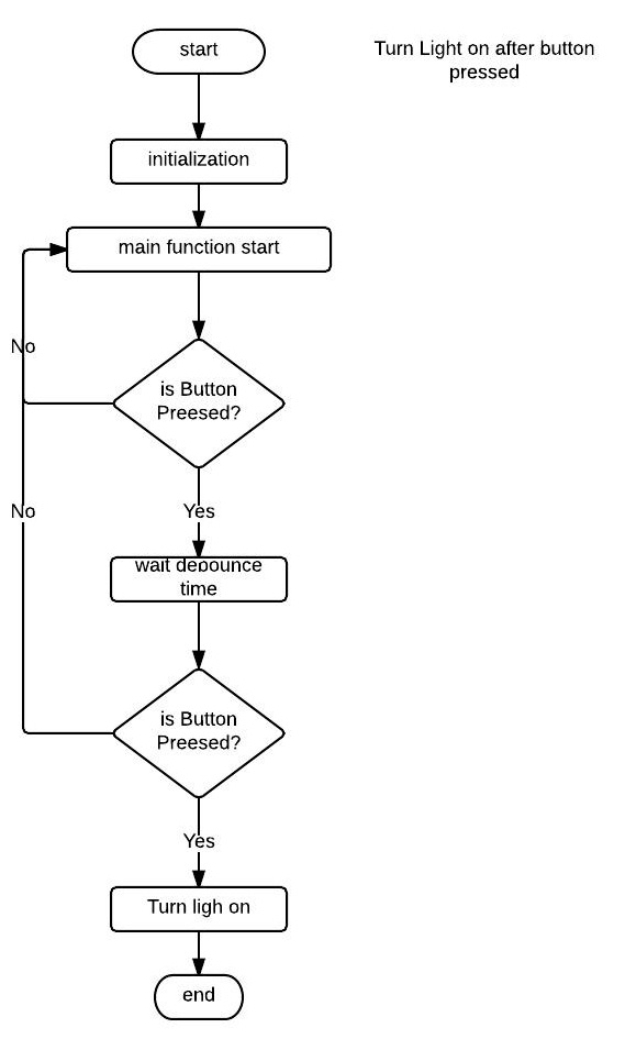 |
| Flow chart |
First lets take a look on the schematic:
 |
| Circuit of today's project |
This is a very simple schematic, at the PORTC<0> we connected the led with a small resistor, and at the PORTA<0> we connected the push button with a pull up resistor. So when the user pushes the button the Vdd wil be applied to the microncontreller PORTA<0>, as a logic "1".
Below you can see the code i created based on the flow chart above.
- ........
- ;***** VARIABLE DEFINITIONS (examples)
- #define COUNTER_us 0x20
- #define COUNTER_ms 0x21
- #define COUNTER_100ms 0x22
- .........
- .........
- start
- ; remaining code goes here
- call Initialization
- main_routine
- btfss PORTA, 0 ;if PORTA<0> == 0 ask again
- goto main_routine
- call Delay100ms ;if PORTA<0> == 1 execute this
- btfss PORTA, 0 ;if PORTA<0> == 0 ask again
- goto main_routine
- enable_led
- bsf PORTC, 0 ;if PORTA<0> == 1 execute this
- goto enable_led
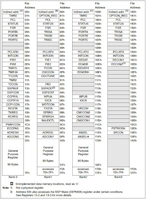
- Initialization
- bsf STATUS, RP0
- bcf STATUS, RP1 ;bank 1
- movlw 0xff
- movwf TRISA ;PORTA is input
- clrf TRISB ;PORTB is output
- clrf TRISC ;PORTC is output
- bcf STATUS, RP0
- bsf STATUS, RP1 ;bank 2
- clrf ANSEL
- clrf ANSELH ;set all I/Os as digitals
- bcf STATUS, RP1 ;bank0
- clrf PORTC
- clrf PORTB
- return
- goto start ; loop forever
- ; initialize eeprom locations
- ;subroutines
- Delay100us
- movlw d'31'
- movwf COUNTER_us
- delay100us
- decfsz COUNTER_us, 1
- goto delay100us
- nop
- nop
- return
- Delay1ms
- movlw d'9'
- movwf COUNTER_ms
- delay1ms
- nop
- nop
- nop
- nop
- nop
- nop
- nop
- call Delay100us
- decfsz COUNTER_ms, 1
- goto delay1ms
- nop
- nop
- nop
- nop
- nop
- return
- Delay1.5ms
- call Delay1ms
- call Delay100us
- call Delay100us
- call Delay100us
- call Delay100us
- movlw d'31'
- movwf COUNTER_us
- decfsz COUNTER_us, 1
- goto $-1
- nop
- nop
- return
- Delay100ms
- movlw d'98'
- movwf COUNTER_100ms
- delay100ms
- call Delay1ms
- decfsz COUNTER_100ms, 1
- goto delay100ms
- ;+ 700us
- movlw d'16'
- movwf COUNTER_100ms
- call Delay100us
- nop
- nop
- nop
- decfsz COUNTER_100ms, 1
- goto $-5
- nop
- nop
- nop
- nop
- return
- .......
Then, as we used to, we have to use the initialization subroutine in order to set digital/analog and inputs/outputs.
The main program starts at line 12, where a loop will run forever until the input becomes high, when this happen we move to line 15 where we call a debounce delay (you could use less than 100ms) and after that small delay we check if the input is still high, if not that means that was a "false alarm" so we go back to line 12 and wait again, but if the input is still high we move to line 18-19 where the command bsf makes the output high and ...voilà!!! The led is ON!!!
 |
| Enabling led |
You can find all the files of that article here.